FFF/FDM 3D Printing Services
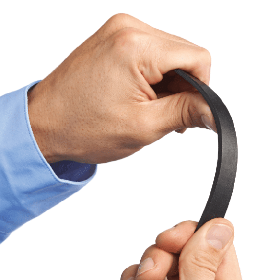
3D Printing Strong, End-Use Parts
A traditional 3D printing process using layers of thermoplastic filament to create durable, lasting parts
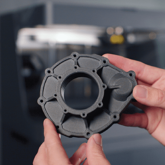
Our FFF/FDM capabilities combine large build volumes with specialized materials, allowing you to produce a wide range of functional parts.
From small fixtures to large aerospace prototypes, there is a 3D printer and material to fit your project’s specific needs.
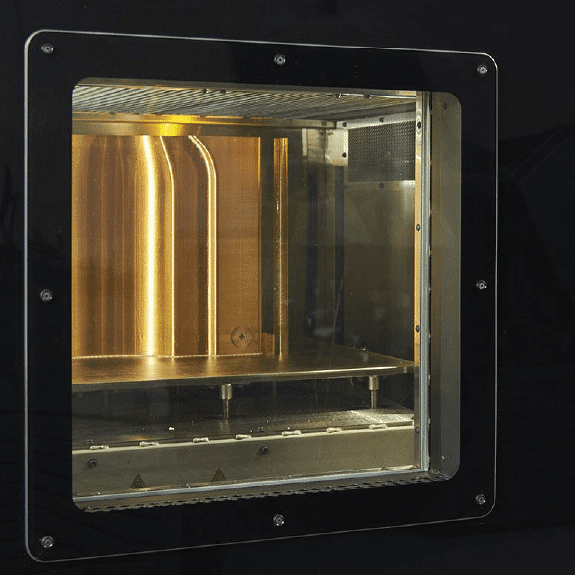
How FFF/FDM Printers Work
To begin the FDM/FFF process, a CAD file is sliced into layers using software that communicates where material needs to be extruded on each layer.
There are two types of material for this: support material and actual part material.
Once the layer receives the sliced file, printing begins by heating the filament and extruding it layer by layer. After the part is made, the support material must be removed manually or with a solution.
Explore Popular Uses for FFF/FDM 3D Printing
- Manufacturing aids: jigs, fixtures, drill guides, locating tools, go/no-go gauges
- Large, flat parts
- For applications where thermoplastics are essential to function
- Robust prototypes
Technical Specifications
|
|
FFF/FDM 3D Printing
|
|---|---|
|
Lead Times
|
Standard: 3 – 4 days | Expedited: as soon as next-day
|
|
Standard Accuracy
|
Typically within +/- a single build layer thickness for the first inch and +/- .002″ for every inch thereafter.
|
|
Standard Build Layer Thickness
|
50-200 microns (depending on material selection).
|
|
Build Envelope
|
Composite Printer: 330x270x200mm (XYZ) | All Others: 36 x 24 x 36″ (XYZ)
|
|
Finish
|
Painting, inserts (including inside the part-must be reviewed), or vapor smoothing.
|
|
Available Fiber Materials
|
Carbon fiber, Kevlar, HSHT Fiberglass, Fiberglass
|
|
Other Materials
|
Onyx, ABS, ASA, Nylon 12, Nylon 12 CF, Polycarbonate, PC-ISO (medical grade), PC-ABS, Ultem 9085, Ultem 1010
|
Frequently Asked Questions
A3D Manufacturing is staffed with materials science engineers to help you in determining which material is right for your application.
A3D Manufacturing is staffed with applications engineers to help you in determining which process (and potentially post processing) needs you might have for your application.