FFF & FDM 3D Printing Services
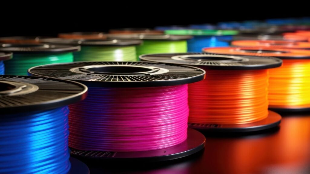
Get durable, functional components in production-grade materials like Ultem, PC-ABS, and carbon-filled nylons.
Is FFF & FDM Printing Right for Your Part?
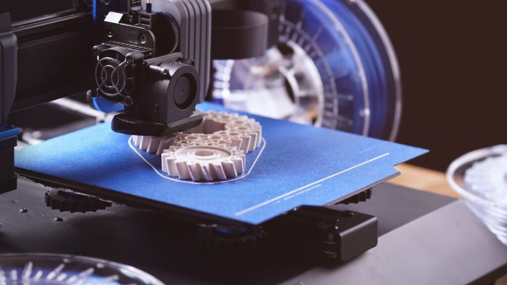
How FFF & FDM Works
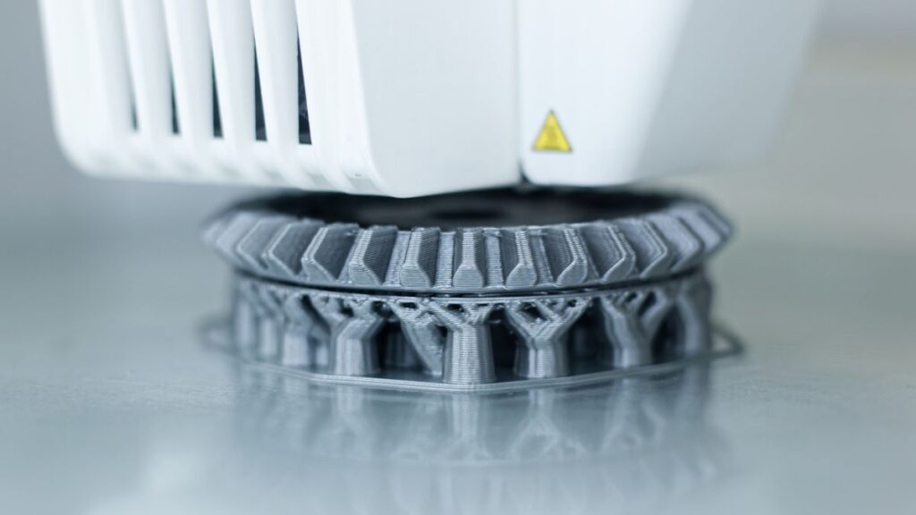
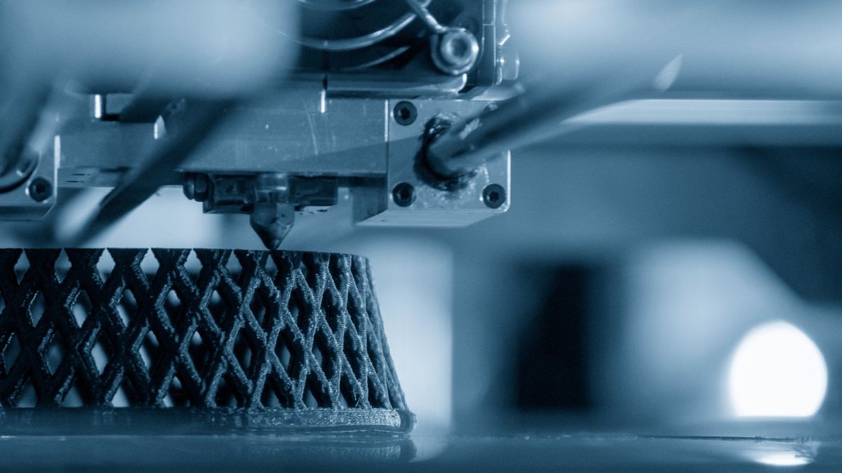
FFF (fused filament fabrication), also known as FDM (fused
deposition modeling), extrudes heated thermoplastic filament
layer-by-layer to build robust parts. It’s a reliable way to
produce strong, accurate components with fast turnarounds
and broad material options.
What are FFF & FDM Ideal For?
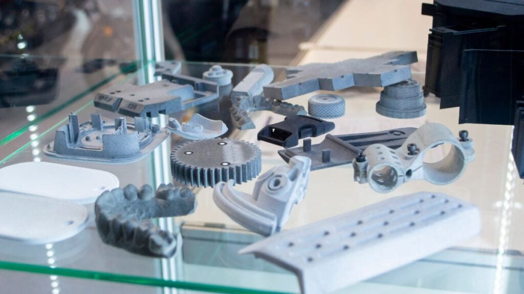
- Manufacturing aids, such as jigs, fixtures, drill guides, and
go/no-go gauges - Large, flat, or robust geometries that benefit from strong
thermoplastics - Functional prototypes and low-volume end-use parts that must
perform in real environments - Industries, such as aerospace, industrial, medical, and high
tech, where consistency and documentation matter
At a Glance: Advantages vs. Other Processes
At A3D Manufacturing, we offer application-first guidance and hybrid
workflows. Our approach is process-agnostic: we guide you to the
right method for your outcome, not just what’s convenient.
FFF & FDM 3D printing advantages include:
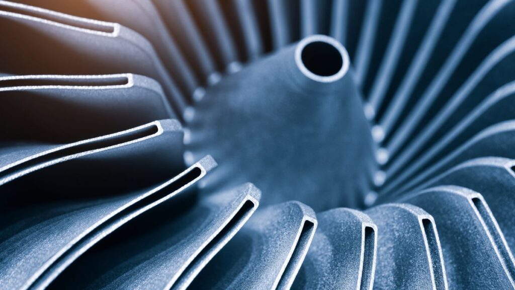
- Tough, end-use thermoplastics (such as PC-ABS, Ultem, and
Nylon 12/CF) for impact, heat, and chemical resistance - Large build volumes for sizable parts and fixtures
- Predictable tolerances and practical design rules for repeatability
- Faster iterations without tooling
- Easy design updates across builds
FFF & FDM Capabilities & Technical Specifications
Lead Times
- Standard 3-4 days
- Expedited as soon as next-day
Tolerances
- X/Y: 0.005″, or 0.002 in/in, whichever is greater
- Z: Above tolerances +/- a layer height
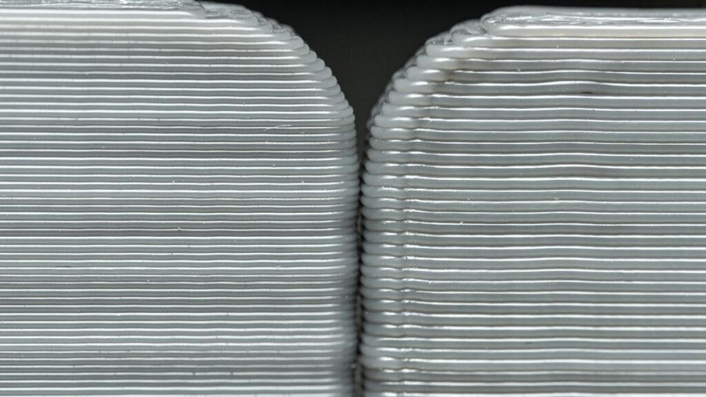
Layer Thickness
- 50–500 μm (material-dependent)
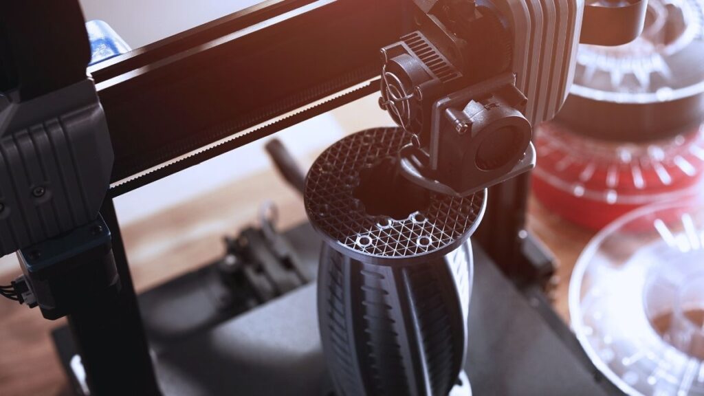
Build Envelope
- Composite printer 330 × 270 × 200 mm (XYZ)
- Others up to 36″ × 24″ × 36″ (XYZ)
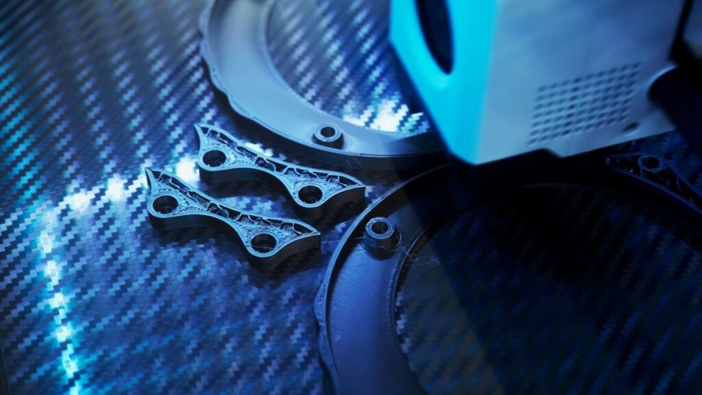
Materials: Fiber
- Carbon fiber
- Kevlar
- HSHT fiberglass
- Fiberglass
Materials: Thermoplastics
- Carbon fiber
- Kevlar
- HSHT fiberglass
- Fiberglass
- Polycarbonate
- PC-ISO (medical-grade)
- PC-ABS
- Ultem 9085
- Ultem 1010
Post-Processing Options
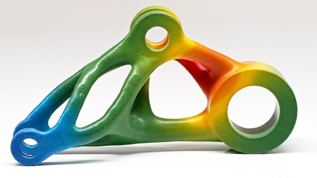
- Painting
- Inserts (including captured hardware and review required)
- Vapor smoothing
- Plus downstream finishes available through our broder post
processing cell
Quality & Compliance
AS9100 • ISO 9001:2015 • ITAR Registered
We apply rigorous certification standards to every project,
ensuring you receive the highest quality products on time, every
time. You can expect your parts to route through A3D
headquarters in Phoenix, Arizona for final QA – no blind drop
shipping – so you get predictable outcomes with documentation
when needed.
Why this matters to you
- Engineers: tighter control, fewer surprises, faster validation
- Startups: scalable production without new vendor risk
- Supply Chain: traceability, documentation, and consistent delivery from a single accountable partner
Common FFF & FDM 3D Printing FAQs
We support STEP or STL.
These are our typical guidelines:
- Minimum Wall Thickness: 0.040″ is commonly accepted (dependent on material and nozzle size)
- Minimum Clearance for Asssemblies: 0.020″
- Minimum Feature Size: 0.020″ (dependent on layer height)
- Minimum Hole Diameter: 0.060″ for X/Y axis; 0.040″ for Z axis
- Minimum Unsupported Overhang Angle: 40 degrees
Our pricing correlates to material consumption and printer build tone. Support-reducing orientations, infill
choices, and layer height all impact cost.
Our materials and applications engineers can recommend the right material, process, and post-processing for
your use case – including MJF/SLS/SLA or CNC if those are better fits for cost, weight, or performance.